Pinion Alignment with Axle Shims on a Jeep Cherokee

Pinion Alignment with Axle Shims on a Jeep Cherokee

When lifting a Jeep Cherokee, the pinion angle changes relative to the transfer case. The alignment must be within the limits of the universal joints to prevent driveline vibrations.

One method of adjusting the pinion angle is to use angled shims. These shims are placed between the spring and the spring perch to rotate the pinion to match the drive shaft.

When a Jeep is lifted three inches or more, the drive shaft angle exceeds the recommended limits for the universal joints. A common method to correct the alignment while retaining the stock drive shaft is to drop the transfer case one inch and use two degree shims or use angled lift blocks like the Rough Country Lift kit includes.

In order to eliminate the misalignment, a Slip Yoke Eliminator kit is often used on the rear of the transfer case. Several versions are available for the NP231 that replace the output shaft with a stronger, shorter shaft giving multiple advantages for one simple modification.

With a Slip Yoke Eliminator kit installed, the standard drive shaft is replaced with a double cardon type like the one used in the front of the Cherokee. In fact, if you have an automatic transmission, a stock front shaft can be used in the rear with a SYE conversion.

The double cardon type shaft however uses a very different alignment from the standard shaft. Quite a bit of axle rotation is needed to align the pinion.

In the standard configuration, the pinion and the transfer case are aligned to be parallel to each other. The idea is to have the same operating angle for both universal joints on the drive shaft.

The double cardon shaft uses a special joint with two universal joints at one end and a singe joint at the other end. The correct alignment is to have the drive shaft parallel to the pinion and the entire angle is made up in the two joints on the opposite end.

For a three inch lift, I found about 8 degrees of shim was needed. This Jeep was fitted with two degree blocks so adding six degrees of angle to the spring pack brought it into alignment.

To calculate the shims needed, you will have to use trigonometry. However it is not too bad using this simple method.

With the transfer case and axle in place, I mounted the drive shaft. The misalignment was immediately evident. I placed a straight edge along the bottom of the pinion and parallel to the pinion shaft. I then measured the distance from the drive shaft center to the top of the straight edge. In my case, I measured to a point 30 inches up the shaft and found it need to be raised three inches to make it line up.

Now divide the distance it is off by the distance up the shaft. In my case it was 3 divided by 30 or 0.1.

To convert this number to the angle, you need to take the arctangent of the number. This is easily done on a scientific calculator or even easier to do using Google. In my case I typed arctan(3/30) in degrees into the Google search line. Google returns this result: arctan(3 / 30) = 5.71059314 degrees. Round it to the nearest degree and try that shim. In my case a six degree shim was really close and worked fine.

To install the shim, you have two options. If you get a steel shim, you can weld it to the spring perch making it a permanent part of the axle. I chose to add it to the spring pack so that it can be easily changed if I want to add longer shackles or different lift blocks.

To install the shim in the spring pack, you will have to disassemble the spring pack. It is generally a good idea to replace the center pin and the shim kit came with new center pins. So you can just cut off the nuts from the center pins. They are often impossible to unbolt due to dirt and corrosion.

Begin by removing the U bolts that hold the axle to the spring. Separate the spring from the perch. Next, use two large C clamps to hold the spring pack together while you remove the center bolt.

Place the new bolt through the shim and then pass the bolt through the spring pack. Tighten the nut. Be sure the fat end of the shim is to the rear to rotate the pinion up for the Cherokee. Align the pin with the block or spring perch and press it back together with a floor jack under the axle. Cut off the excess bolt length on the center pin.

Reinstall the U bolts and tighten them to the proper torque. Give it a good whack with a hammer to make sure every thing seated right and recheck the torque. It is good to recheck the U bolts after the first run as they sometimes move around on the axle tube and loosen up.

Verify the alignment visually or with a straight edge. If it looks right, congratulations! Put the wheels back on and give it a test drive.
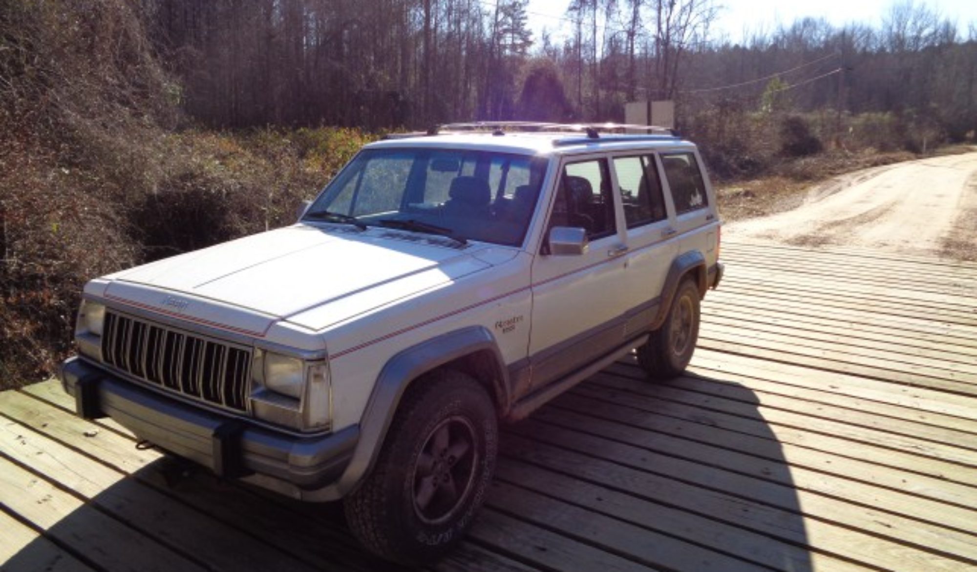
Rough Country Suspension Suspension Lift Kit

Golden Mountain Off Road Park – Labor Day

Golden Mountain Off Road Park.

We celebrated Labor Day and Princess’s birthday by going off roading at Golden Mountain Off Road Park. I spent the early part of the weekend installing Princess’s SYE equipped 231 Transfer case and getting the pinion angle right in the rear. But by Monday, we were ready to hit the trails.

Our previous visits to Golden Mountain had been last fall when the trails were wet and slippery. This trip they were dry and dusty.

At the park entrance we were greeted by the very friendly park owners. They made us feel very welcome.

After unloading my truck from the trailer and removing the doors from both Cherokees, we headed up trail one. Trail one has always been our nemesis in the wet. It is marked easy on the map but even in dry conditions it is challenging. On our previous attempts is has proven impassable.

This time we made it all the way to the top. Coming back down the other side of trail one proved to be even more of a challenge however. This part of the trail has eroded into a deep V notch right down the center of the trail. The only real way down is to straddle the V. I made it fine but Jenny got hung up in one of the transitions. I had to help her get untangled.

Once down from there, we headed up trail 11. This is a fun rocky climb. There was a spot where Jenny got hung last time, but this time equipped with lockers, a SYE and no doors, she made it easily.

At the top of 11 we made our way to 12 and made the loop. Trail 12 has several rocky sections and then ends in a long hill climb. Jenny got hung in a muddy spot last trip, but there was no mud to hang in this time. Just lots of dust. The dust made some of the climbs slippery, but not like the mud.

We took trail 29 down to intersect with trail two and took a break. This was our first time on 29 with was pretty easy in the dry but would be very slippery if wet.

After a rest break we headed up trail two to Jenny’s favorite ledges. Again they were much easier in the dry.

At the top, we toured the pavilion and the camping areas. Here I noticed my Jeep was running very hot. I soon discovered that the electric fan was not working.

We made the short trip down the paved road to the trailer and I scavenged wire from Jenny’s Jeep to make a jumper for the fan. I simply wired it directly to the battery so that meant every time I stopped for any length of time, I had to open the hood and disconnect the wire.

We headed back up the trail and made the 12, 29, 2 loop again. This time we decided to try an unmapped spur off trail 11. This brought us out at one of the pavilions across from the lake. My Jeep was still running hot so I let it cool and added some water.

Scott called and we arranged to meet him at the gate. After picking him up, we ran back up trial one again. This time we took trail 10 on our way to see the top of bounty hill. Trail 10 we found has a very scary section where you have to make two very steep drops in about the length of the Jeep. Scott spotted me down and then did the same for Jenny. I was really glad we did not have to go back up that section.

The climb back out of the hole was still pretty challenging as it is a steep rutted climb. The climb ends with a choice of two big boulders that you have to climb the face of. I did not want to loose momentum, so I made a quick decision of the one on the left. That turned out to be a good choice and I made it up easily. I got out and was able to spot Jenny to the smaller boulder as well.

My Jeep was running much better with the fan on and the radiator full of water. I was really glad that I was able to make a simple fix.

We took time to climb on the boulders overlooking bounty hill. I have watched videos of buggies going up it but I would really like to see one in person.

Next we went down trail 27 to one and made our way to 21. This required running the same part of one that gave us trouble earlier in the day. Jenny got hung up in the same spot again. With Scott spotting me I drove her Jeep up onto the bank and out over the V notch. At one point Scott said the front tire was about two feet in the air but it did not feel tippy until it had already started back down.

We drove up 21 and took a look at Hellivator and some of the other climbs in the same area. We all agreed that we look forward to watching someone do these climbs.

We turned around and headed back down trail 21. We took 11 for the third time just because it is fun and took the exit by the small pavilion. We stopped again to tour the big pavilion and take advantage of the facilities there. Caleb enjoyed the playground for a while too.

We headed back into the trail 12 loop and then took 29 back down and then exited on the lower part of trail 2. By the time we made it back to the trailer, we were all very tired and dusty, but we really enjoyed our day at Golden Mountain.

Installing a Slip Yoke Eliminator (SYE) in a Jeep Cherokee

Installing a Slip Yoke Eliminator (SYE) in a Jeep Cherokee

This weekend I installed in Jenny’s Jeep Cherokee the SYE equipped 231 that I built last fall. Our plan was to use a stock front drive shaft in the rear and to remove the transfer case lowering blocks that had to be used to align the drive shaft previously.

Before I began, I coated my hands with Market America Clear shield.

I began by removing the original transfer case. As described in a previous article I installed the SYE in a spare 231 case. The Slip Yoke Eliminator kit can be installed with the transfer case still in place under Jeep.

I began by draining the fluid from the transfer case. Then I removed the rear drive shaft and disconnecting the front shaft from the T case. To remove the transfer case, I supported the transmission and dropped the cross member. I also disconnected the exhaust that the cat flange to get a little more working room.

Next I used a 9/16 box end wrench to remove four of the six bolts that hold the transfer case to the transmission. I used a socket and long extension to get to the two behind the linkage bracket.

With the old transfer case out of the way, I put the modified case up. I had an assistant turn the output shaft to align the splines while I pushed the case into place. Then I tightened the six nuts that hold the case in place.

I lifted the transmission back into place and reinstalled the cross member. Next I reconnected the exhaust and the shift linkage. Then I filled the case with fluid.

The trouble began when I went to hook up the rear drive shaft. The shaft that I had pulled for this purpose would not reach. It was simply not long enough. It also had trouble sliding on the slip joint. So, I rummaged around the barn and found another front shaft. This one slipped in and out easily and reached just fine.

We bolted up the front shaft and took it for a short test run. A very short test run. As soon as we backed it out of the barn, it was obvious that the advice we had read in an internet forum about what shims to use was completely wrong. The drive shaft angle was completely wrong.

I made a few measurements and found we needed 7 degree shims. A call to our local 4wd shop revealed they did not stock them. We chased a few leads they gave us only to find dead ends. As we were ready to give up for the day and possibly the weekend, Jenny used her new Droid phone to research and found Summit racing, 142 miles away, had them. She called and found they had six and eight degree shims in stock but no sevens.

I expected our trip to Golden Mountain was postponed again, but she jumped in my truck and was waiting for them to open the next morning and had shims back at the shop by noon. Determined to go off roading this one is.

I unbolted the spring pack and installed the six degree shims. With it all back together and better aligned, we took it for another test drive. Much better, but there was still a nasty vibration.

Back in the shop I found that the shaft I had grabbed had a lot of play in the double cardon part. So we swapped her front shaft to the rear and made a test run. This time it was vibe free.

I hammered the other shaft apart and greased the splines to get it to slide. Once it was flexible enough I installed it in the front. A quick test run showed some noise but the vibes were at an acceptable level.

Monday we packed up and drove 111 miles to Golden Mountain Off Road Park in Sparta, TN. She had no problem going seventy miles per hour on the interstate following me with my rig on the trailer.

The SYE equipped Jeep handled very well on the trails. Jenny enjoyed the extra clearance that she got from removing the spacers as well.

[phpbay]slip yoke eliminator, 10[/phpbay]

Trail repair of Jeep Dana 30 Axle or U-joint

The Jeep Dana 30 axle will hold up under most conditions, but when you start adding larger tires and lockers as well as driving in more rugged terrain, there is always a chance something might break. Having the right tools and spare parts on board can save the day. A broken axle shaft or U-joint can be changed on the trail in about 20 minutes providing you are properly prepared.

Things you will need include; a jack, a spare shaft, a 13mm twelve point socket or wrench, a 36MM socket and something to turn it. You will also need the appropriate tools to remove your wheel and brake caliper. These vary from year to year and depending on your accessories. A hammer and a spare set of hub bolts will be helpful as well.

If your wheels have open centers, begin by removing the cotter key and the center nut on the axle shaft. This nut is very tight when tightened to specs. You will need either an impact wrench if you have on-board air or a long handled pull bar on the socket. If you have a closed center wheel, you will have to remove the wheel and have someone hold the brake while you loosen the nut.

Support the vehicle and remove the wheel. Remove the brake caliper and support it on the control arm. Try not to let it hang by the hose. Next, remove the brake rotor.

Using a 13mm 12 point socket, remove the three bolts that hold the bearing to the knuckle. The bearing will likely be stuck in the knuckle. My favorite way of removing it is to screw in some disposable bolts that have the same thread and hammer on the bolt heads. Once you hit the bolt head with a hammer, you will not be able to put a wrench on them in the future. I carry a set of bolts for this purpose in my axle repair kit.

If you don’t have spare bolts, you can still tap the bearing out using a hammer and pry bar. Try not to hit on the wheel mounting flange however as this can damage the bearing.

Slip the bearing out and then remove the broken shaft. If part of the shaft remains in the axle housing, use a magnet to remove it. If you can not pull it out with a magnet, you can also remove both shafts and push it out with a stick or long metal rod.

If you have jacked up the side you are working on high enough, you will not spill any axle grease. Even with it level, there should only be a small loss.

Slip in the spare shaft and check for any other damage. Put the bearing back in place and secure the three bolts. Place the rotor back on the hub and secure the brake caliper. Mount the wheel then tighten the center axle nut. Replace the retainer clip and cotter key.

Pump the brake pedal a couple of times to remove any slop that may have been introduced by removing the caliper before attempting to move the Jeep. Now get back to wheeling!
[phpbay]jeep axle, 10[/phpbay]

Automatic wheel balance

Balancing tires

I have dealt with many different ways to balance tires since I started mounting my own tires several years ago. I have had very good results using a simple bubble balancer and lead weights clamped to the rims.

I have considered purchasing a spin balance machine on several occasions but the cost of the machine has deterred me considering the small number of wheels I balance in a year. I can pay to have several tires balanced for the cost of a machine. Also, for most tires my bubble balancer provides acceptable results.

I have studied various methods of automatic wheel balancing for years as well. As the tire wears, the balance changes. And short of taking the tire off the Jeep and rebalancing it, there is nothing else that can be done using the clam on wheel weight method.

I have looked at the rings full of mercury that bolt on the back of the wheel. I have studied the sand and ceramic dust methods used on semi trailer tires. However the simplest method for me to implement would be to add a liquid to the tire.

Looking at the mathematical proof of the physics behind the sand method, I theorized that any fluid would do the same. The material tends to move to the light spot as centripetal force takes over automatically balancing the tire as it rotates.

This week I came across the idea test subject. In the past I was fighting other vibrations at the same time such as bad bearings or U joints. This time however, my truck was running smooth and I had a tire with a big chuck of rubber missing.

Running the tire with no weights produced a huge bounce that could be felt at speeds over 40mph. The Jeep was un drivable at over 60MPH.

The first test was to balance it with conventional lead weights in the bubble balancer. It took slightly over 280 grams of lead on the rim to balance the tire. It was difficult to get that much lead on the wheel and on the test run one of the weights came off. However it did produce a smooth ride.

The next test was to replace the lead with a liquid. I did not want to use water as in freezing conditions it would make a block of ice in the low part and create a huge imbalance. I chose instead a 50/50 mix of antifreeze and water.

I popped the bead on the tire and poured in 290 grams of the balancing liquid. I remounted the tier and took it for a test run.

The initial test run showed a nice smooth ride. I was not able to exceed 60MPH on the test run due to road and traffic conditions but the ride was noticeable smoother than with the lead weights.

I plan to further test the liquid wheel balancing method to see if it will automatically balance all wheels. The math shows that it will work with tires that have dynamic balance problems as well. I can’t deal with these on my bubble balancer so if the liquid method of automatic wheel balancing works, I will not ever have to buy a balancing machine.
[phpbay]tire balance, 10[/phpbay]