Jeep MAP sensor error

Clearing MAP sensor code

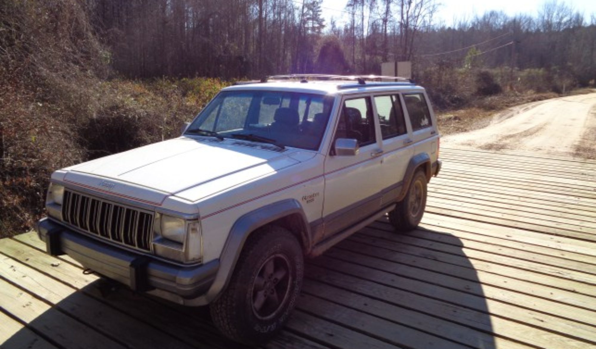
Yesterday while I was repairing the door hinge on a friend’s Jeep Cherokee, I noticed it had been running rich. I checked the ECU codes and found code 13 and 52. 13 is an unresponsive MAP and 52 is O2 rich.

I first swapped in a spare MAP, cleared the codes and started it up. I got he same rough idle and soon the same code in the Check Engine light.

With the engine still running, I pulled off the vacuum line and noticed there was no vacuum. The line looked fine. I pulled off the other end and found vacuum at the manifold. The line was obviously clogged.

As I was walking to pull a spare off the parts rig, I noticed a tiny spot on the bottom of the line that was melted. I never found the source of the melting, but the Jeep ran much better after replacing the plastic hose. The MAP and Rich codes cleared up as well.

How to change the power steering pump on a Jeep Cherokee

How to change the power steering pump on a Jeep Cherokee

Begin by removing the air cleaner box. There are three bolts in the bottom that are access by removing the filter. Be careful when separating the various air line form the box.

Begin by breaking loose the high pressure line. This is a 5/8” hex on most Jeeps.

Remove the low pressure return line as well.

Loosen the jam nut on the belt adjuster under the pump and loosen the drive belt.

Next remove the three bolts on the back of the power steering pump.

Remove the pivot bolt on the front of the pump.

Remove the bracket and pump as an assembly.

Use a pulley removal tool to remove the plastic pulley from the pump. Most Auto parts stores have these as loaners for this job.

Put the two halves of the puller together over the groove in the pulley and the tool. Slide the sleeve over the two halves. Turn the bolt to press off the pulley.

Now remove the bolts that hold the pump to the bracket.

Bolt the new pump to the bracket.

Press the old pulley onto the new pump using the press in the kit.

Thread the stud into the treads in the pump shaft. Place the pressing washer over the stud. Turn the nut to press the pulley into place.

Mount the bracket back on the engine and reconnect the lines.

Adjust the belt tension

Replace the air box and filter

Reconnect the air lines

Fill the reservoir with new fluid but do not start the engine.

Note, if the old fluid looked contaminated, milky or black; you may want to flush the system before continuing. Follow the instruction in the pump kit.

Turn the wheel from lock to lock

Check the fluid level and top up if needed.

Start the engine and again rotate the wheel from lock to lock slowly.

Check the fluid level again and refill as needed.

Check for leaks and correct any you find.

Replace the cap.
[phpbay]jeep steering, 10[/phpbay]

How to remove a Jeep Cherokee Brake Caliper

How to remove a Jeep Cherokee Brake Caliper

There are two different brake calipers used on the Jeep Cherokee. The earlier Jeeps, 1990 and before, use two cylinders with 7mm hex key slots. The later, 1991 and newer, use two 13 MM blots to hold the caliper in place.

In either case, begin by lifting and securely supporting the Jeep.

Remove the wheel.

To improve access you can rotate the steering so that the brake caliper is facing out. However unless you have longer than stock brake lines, don’t turn it all the way or you will have trouble getting the caliper off the brake pads due to the brake line.

Remove the mounting bolts or cylinders using a 7MM hex bit or 13MM socket as needed for your year.

On the earlier models, the ones with he 7mm cylinders, the brake pads stay in place and the caliper slides off them. On the newer ones, the pads come off with the calipers.

In either case use a pry bar to rotate the top of the caliper back to slide it off. On the newer one, if there is a groove in the rotor you may have to push the pads back into the caliber slightly to get it to slide off. In severe cases, you may have to loosen the bleeder screw to get it to compress.

When replacing the earlier style it is a good idea to replace the Teflon sleeves that go around the cylinders when you replace that caliper. At least inspect them before reinstalling the caliper.

Sometimes the caliper can be stored by placing it over the lower control arm. In most cases it is best to use a wire to tie it up while the other brake parts are being serviced. Do not let it hang by the brake hose.

If new brake pads are being fitted, you will need to compress the piston back into the caliper before they are refitted. I use a large C clamp to push the piston in. Or you can use a caliper compressor tool.

To replace the caliper, slide it into place and carefully feel for the fit of the retaining bolts or cylinders. They should start easily by hand. If not remove the caliper to see why it is not aligned. These bolts can be easily cross threaded and a thread repair is not easy on the knuckle. So avoid cross threading by carefully aligning the caliper when reinstalling securing bolts or cylinders.

Reinstall the wheel and properly torque the lug nuts.

Before moving the vehicle, be sure to pump the brake pedal a few times to take up any slack that was generated by pressing the piston back in.

How to repair a leaking valve cover on a Jeep 4.0

How to repair a leaking valve cover on a Jeep 4.0

Repairing a valve cover leak
Jennifer and Hunter prepare to repair her Jeep's valve cover leak

The early Jeep 4.0 valve cover is sealed with RTV silicone. However after 1995, Jeep used a rubber coated metal gasket. Be sure to get the right seal before removing the valve cover to repair a leak. The proper silicone is oil resistant. You can get it from a Jeep Dealer or from some aftermarket suppliers such as Crown Automotive.

Begin by removing the cables going to the throttle body. These unclip from the throttle body and the bracket between the throttle body and the valve cover. Label them and lay them aside.

Remove the crankcase vent tubes.

Next, remove the hose supports and spark plug wire holders that may be attached to the longer studs of the valve cover retaining bolts.

Make a cardboard or Styrofoam template of the valve cover and use this template to keep track of the various types of bolts used to secure the cover. They need to be installed in the same holes they came out of.

Remove all the bolts. They are typically 11mm and you will need a deep well socket for the studs. On the Cherokee, there is one in the back near the firewall that can be difficult to access. I use a 3/8 drive socket mounted on a universal joint to access it.

With all the bolts out, carefully bump the cover with your hand or a rubber hammer to break the seal. Carefully lift it off the head taking care not to drop trash into the valve area.

Scrape off the old gasket material. If you are working the earlier RTV type seal, a Scotchbrite wheel on a drill can be helpful to clean the cover. I mount mine in my drill press to make it easier to handle.

Clean the head mounting surface as well.

For the gasket style, simply place the gasket on the head. Pay attention to the two locating dowels to make sure the gasket is properly aligned. For the RTV style, apply a thick even bead of silicone to the cover and let it sit for about five minutes before installing the cover.

Set the cover in place and make sure it is aligned properly. Make sure that none of the wires or other tabs are trapped between the cover and the head.

Using your template, put the bolts and studs back into the holes they came from. Tighten them snugly but not too tight. These are small bolts.

Replace the holders on the studs and put back any nuts that were removed.
Reconnect the cables to the throttle body.

Reconnect the crankcase vent lines.

Take a moment to check for any other lines that may have been knocked out of place. It is easy to pop out the line to the MAP sensor or the fuel pressure regulator while removing or replacing the valve cover.

The gasket style can be started immediately and checked for leaks. The RTV style needs to set at least half and hour before starting.

How to replace the AC compressor on a GMC 1500

How to replace the AC compressor on a GMC 1500, 2500 or 3500

Replacing the AC compressor on a GM 350 engine is not nearly as hard as it looks. The compressor is held to the engine by an aluminum cradle. The cradle does not have to be removed to replace the compressor. There are simply three bolts that hold the compressor to the cradle that have to be removed.

Note that this procedure only covers the physical swap of the compressor, not he associated tasks related to servicing the AC system after a compressor failure.

Begin by removing the freon from the system. If you want to have it reclaimed, take it to a shop that does this.

Remove the two electrical connections to the compressor.

Next remove the freon lines form the back of the compressor. The manifold is held in place by a single bolt. Mine was 15 MM.

Use a pry bar to move the belt tensioner and slide the belt off. I found the easiest pulley to get the belt off of was the smooth idler below the compressor.

With the freon lines out of the way, the bolts are much easier to access. There are nuts on the back and the bolt heads are held in place by a boss on the front. Mine were 9/16”.

With the nuts removed the bolts can be pushed out the front. However, it appears that they will not clear the clutch. However, there is a flat cut on each bolt. Rotate the flat to be next to the clutch and the bolts will slide out. A pry bar can be used to get just a little extra clearance if the bolt does not slide past easily.

On mine, one bolt also interfered with the fan shroud. I found that by removing the bolts that hold the shroud to the front header, the shroud could be moved enough to get the bolt out.

With the bolts all out, the compressor simply lifts out of the cradle.

With the compressor out, I had to swap a pressure switch that did not come with my replacement compressor. This switch is held in place with a snap ring.

Before attempting to slide the new compressor back into the cradle, take time to tap the bolt hole inserts all the way to the back of the cradle. This will make inserting the new compressor much easier. They will press back into the proper place when the nuts are tightened.

Slide the bolts back in by again aligning the flat spot on each bolt with the clutch and slide it in. Place the nuts on each bolt and tighten.

Reconnect the electrical connections to the compressor.

Secure the fan shroud.

Make sure the belt is routed correctly and use a pry bar to move the tensioner and slip the belt back in place.

Add the proper amount of oil and reattach the freon lines to the compressor.

You can now have the system serviced and the freon replaced.