Vibration Diagnosis

Diagnosing the vibrations in my Jeep

For a while now I have had severe vibrations in my street Jeep. I have corrected several problems like a bad front pinion bearing and a drive shaft U joint. However the vibrations have persisted.

Every time I drive, I get a shimmy at 50 to 55. On the interstate I can’t go over 70 as it feels like the whole rear of the Jeep is coming off the ground.

I got a new set of BFG AT’s thinking my old worn ones may have contributed to the vibrations. However if anything it made the vibrations worse.

I started with the vibration diagnosis chart in the Jeep Shop manual. Everything there pointed to the tires. But since I had new tires I discounted that. I put the tires back on my bubble balance machine just to make sure but they read fine.

I then set to looking at all the U joints, wheel bearings, ball joints, drive shafts and any thing else that moves with the suspension. I even changed rear springs thinking maybe my sagging springs could have disturbed the pinion angle.

I swapped drive shafts and installed new shocks. The only part not changed was the steering stabilizer.

Last night I decided to look for a bent wheel. I set up my dial indicator on a jack stand and read the rim. It had about .020 maximum run out on any wheel. I figured that was not too bad.

I also checked for out of round on the rims. They all read pretty good.

I also put the indicator against the sidewall of the tire. It was difficult to read due to the moldings on the tore but they seemed to be fine as well. I never figured out a way to read the out of round of the tire due to the tread pattern of the AT. There is no clear path to rotate the tire and not have the indicator fall into the tread.

I also checked the Vibration Analysis chart on the Tire Rack web site. Their chart also indicated a tire problem.


I happened to have another Jeep in the shop that had a fresh set of Goodyear tires that had been dynamically balanced. I decided to put them on and just see.

At 55 it was smooth as could be. Not even a hint of shimmy. I made a quick dash to 75 and it was smooth there as well. No pounding like I have experienced with the new BFG’s.

While I am glad I have found the problem, I am pretty disappointed with my new tires. This is the second set of BFG tires I have dealt with that had a dynamic balance problem. The ones I put on my daughter in law’s Jeep were BFG Long trails and they will not run smooth at high speeds. I have not had that trouble with Kumhos or Michelins.

I guess my next step will be to try a liquid balance on the tires. I really hate to spend $50 or more to get them dynamically balanced knowing that I will have to keep doing it as the tires wear.

Resealing a Differential Cover

Resealing a Differential Cover

Ever since I put the 4.11 gears in Jenny’s Jeep her pink diff cover has had a slight leak. Not much, but enough to make a spot in her parking lot and leave a trail on the gas tank.

We tried tightening the bolts a little more. We tried waiting to see if it would seal its self like some new leaks do. But this one just kept dripping.

Rather than use the method I had learned years ago from Marcus at go.Jeep-xj.info, I had followed the instructions on the RTV tube. This method obviously did not work as well as the method I have used in the past that had never leaked.

We began by lifting the Jeep and preparing a clean catch pan for the diff oil. I was curious to take a look in side the differential anyway to see how the new gears looked.

The RTV had made an excellent seals on most of the cover as it was very hard to get off. The Blue Torch Fabworks cover had no flex like the stock cover so it all has to break loose at once. I had to use a chisel to pop it loose.

With the cover off, the unsealed spot was obvious. The RTV was separated between two bolts on the one side that leaked.

After scraping both surface clean, I applied a thin coat of RTV to the cover. I wiped down the differential housing carefully and made sure that the oil did not continue to drip out at the bottom. I let the RTV skin over for about five minutes before carefully setting the cover in place and starting two bolts so that it did not slide.

I checked the torque specs on the replacements bolts I had for the cover and set my torque wrench. I don’t normally use a torque wrench on the cover bolts but I wanted to make sure this one did not leak a second time. I toqued the bolts evenly in a crisscross pattern.

After letting the RTV set up a few minutes longer we refilled the housing with gear oil. We put some pipe dope on the plug and sealed it up. So far there are no leaks.

If it leaks again I will consider the Lube Locker gasket:

Lube Locker Chrysler 8.25 Differential Gasket

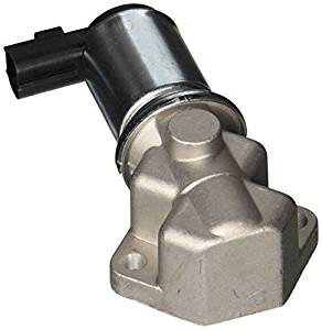
Replacing the Idle Air Controller on a Mazda MPV

Replacing the Idle Air Controller on a Mazda MPV

The idle speed on most modern fuel injected engines is controlled by an idle air control valve. This valve is controlled by the ECU and allows air to bypass the throttle body to maintain the idle speed.

The Idle Air controller on the Mazda MPV is located on the back of the intake manifold. It is held in place by two 10mm head bolts. Just remove the bolts and the old valve can be removed. It is easier to disconnect the wiring harness after the valve is off the manifold.

Install a new gasket and attach the wire to the replacement valve. Bolt the new valve down and you are done.

Start the engine and test the idle speed. The computer may take a moment to adjust to the new valve but the idle should smooth out and now be controlled ending embarrassing and dangerous stalls.

AW4 Troubleshooting

AW4 Troubleshooting
Diagnosis of faults in the Jeep AW4 transmission.

The automatic transmission used in the Jeep XJ Cherokee is nearly bullet proof. Seldom does it ever give trouble. Maybe that is why it is so hard to find good information on how to fix it when it occasionally does act up. The same transmission is used in 600hp turbo Supras so it can handle a lot of abuse.

To test if the trouble is electric or mechanical, pull the fuse to the TCU or disconnect the wiring harness. 1-2 will give first gear only, 3 will give third gear. D will give forth gear. The torque converter will not lock manually. You can drive the Jeep just fine this way until you figure out what is wrong.

If the transmission does not shift as described manually, then you have a serious problem and you need to get another transmission from the junkyard. Don’t buy a rebuilt one. If you have yours rebuilt make sure the shops knows how to handle the AW4. If you choose to rebuild it yourself, the FSM has lots of nice pictures.

Most of the time the trouble will be associated with the Transmission Control Unit or TCU. It is handy to have a spare for trouble shooting although the computer itself rarely goes bad.

A transmission control unit located under the passenger side panel under the glove box controls the AW4. The panel is one piece all the way across and there are more control boxes on the driver side so be careful when you remove it.

There are two controllers that I know about. The 1990 and earlier use a different one from the 1991 and up. Somewhere along the way they combined the TCU and the ECU but I don’t know what year that was. The 1991 and up unit has a green connector. It is not interchangeable with the earlier unit.

The TCU gets inputs from a speed sensor, the Throttle Position Sensor, the brake pedal, the battery and the ignition switch. Some models also have a power / comfort switch.

The only outputs control three solenoids. One controls the torque converter lockup and the other two select the four gears in a binary fashion.

First Gear S1 on S2 off
Second Gear S1 on S2 on
Third Gear S1 off S2 on
Forth Gear S1 off S2 off

As you can see, if the TCU has no power, you will get forth gear in D position. Also with the TCU off, 3 will give you third gear and 1-2 will give 1st gear. You can’t get 2nd manually.

The wires on the 1991 and up TCU are connected as follows:

C3 Speed Sensor Tan
C8 NSS 1-2 Light blue
C9 NSS D Green
C10 Brake switch Light Blue/ yellow
C11 Power switch Tan
C14 Torque Converter White
C15 Solenoid 2 Violet
C16 Solenoid 1 Blue
D7 Ground Black
D14 Battery Red
D16 Ignition Yellow
D1 TPS+ Gray
D3 TPS- Tan / orange

Note that the wire colors and traces may be different on different years. Check your FSM wiring diagrams for the right colors for your Jeep. The pin position is the same on all the TCUs however.

If the speed sensor signal is bad, the controller will force the transmission to stay in first gear. It will not shift at all. Unplugging the controller will give manual operation. This speed sensor is mounted in the side of the transmission under the transfer case shift linkage if you have 4wd. Don’t confuse it with the speedometer sensor in the transfer case.

The brake input is used to unlock the torque converter. The 1990 and earlier used +12 to lock and zero to unlock. The 1991 and up is the opposite.

The TPS voltage should read about .5 volts with the throttle closed and 4.5 volts with it open. It should transition smoothly between the two numbers. It seems to work fine even if the voltage is a little off.

The solenoids are located inside the transmission. They get power from the TCU. You can monitor the voltage to see if they are getting power at the right times. You can also add a power wire and switch to juice up solenoid 2 to get second gear when in the 1-2 position. This gives you control of 2nd gear which is hard to come by any other way.

You can check the solenoids by testing the resistance across the coils. Attach one side of your meter to the battery ground. Good grounds are hard to come by inside the Jeep. Connect the other side to each wire going to the solenoid. They should read around 15 ohms give or take a couple. They seem to read different warm than cold but will be in the teens if good.

The solenoids are expensive and require dropping the pan to change. Make sure you have eliminated other possibilities before swapping one.

Contrary to most wiring diagrams I have seen, the solenoids do not ground through the black wire. They ground to the transmission case. So if you are having trouble with a solenoid energizing, make sure it is properly grounded to the case and the case is properly grounded to the battery before swapping it out.

The speed sensor uses the black wire. If either the black wire or the white wire are damaged in the transmission wiring harness, the transmission may hang in first gear. The harness passes right behind the transfer case shift linkage and can be damaged by the linkage if it is moved around by a transfer case drop or something like that.

Normally, the transmission with switch to 2nd at 20 to 25 mph depending on the TPS signal. It gets its speed reference from the internal speed sensor so if you are in low range, the speed will be different.

In the 1-2 position, the torque converter can lock up in first or second gear. In 3 or D it will only lock in 3 or four. The normal sequence is to shift to second, and then third, then forth and then the torque converter will lock up giving an engine speed of about 2700 RPM at 55 MPH.

Armed with this information, you could be able to sort through nearly any fault in the AW4. The FSM is most unhelpful in that it calls for a DRBII scanner that seems to be unavailable at any price these days. Even if you had one the TCU only gives a few codes that are really not very helpful. You will probably still have to sort through each of the inputs and outputs to find out what is really wrong and get it working again.

Bad Ball Joints Again.

Bad Ball Joints Again.

After breaking a second axle U joint in just a few months time, I had to see what was wrong. While I still don’t really understand why, I know from experience that if the ball joints are loose, the U joints will break.

As I was putting the hub back in after changing the axle shaft, I saw the ball joint move. There should be zero up and down motion in the ball joints. They should only pivot. Mine was moving up and down almost a quarter of an inch. I knew this was trouble so I removed the axle shaft and replaced it with a 2wd stub shaft to wait until new ball joints arrived.

With the new ball joints in hand, I set about removing the old ones. They have only been in pace a couple of years or so. I followed the same procedure I have documented before in: Ball Joint Replacement.

When I went to separate the knuckle from the ball joints, the lower joint split and part came out with the knuckle and part stayed in the axle. I had found my problem. I am still not sure if it was a bad part or was not lubricated properly.

I pressed in the new ball joints using the same procedure described in: Ball Joint Replacement. To reduce stress on my press, I used a hammer to strike the end of the press between turns on the bolts. This trick allowed the press to easily push in the new joints without bending the press as I have done in the past.

The hammer taps help to keep the ball joint aligned as it presses in and relieves and sticking as it moves through the axle. Hammering also helps in the removal process as well.