Replacing the Idler Pulley on a Jeep Cherokee

Replacing the Idler Pulley on a Jeep Cherokee

If you get a strange chirping sound from the front of the engine in your Jeep Cherokee it is likely the idler pulley. These have a replaceable bearing but it generally easier to just buy the whole pulley with a new bearing installed.

To change the pulley, you will first have to loosen the serpentine belt. The belt is adjusted at the power steering pump. On most vintages, the power steering pump moves to adjust the belt. On the later vintages, there is an adjuster beside the power steering pump. Removing the air box makes access easier.

With the belt loose, remove the bolt in the center of the pulley. Most have a 15mm hex. Slip the pulley off and remove the sleeve from the center. In most cases you will reuse the sleeve.

If the pulley comes with a new sleeve, use it instead of the old one. Otherwise put the old sleeve in the new pulley. Bolt it back to the engine.

Reinstall the belt and tighten it up. I found the tension is about right when the belt will only twist 90 degrees between the power steering pulley and the water pump. It has to be pretty tight or it will slip when the AC is on.

Dayco No Slack Idler/Tensioner Pulley - 89097

Replacing the steering box on a Jeep Cherokee

Replacing the steering box on a Jeep Cherokee

The steering box on a Jeep Cherokee rarely goes bad. Mine has over 345,000 miles on it. However, I recently changed one that had been damaged in an engine fire. These instructions will also help if you want to upgrade to a larger steering box.

Begin by removing the air box and electric fan to gain access. Remove the hydraulic hoses. The fittings at the box are 18mm. It may help to have a crow foot line wrench but I always make do with a stubby 18 mm open end.

Remove the bolt that secures the sector shaft to the box. It may not look like it, but the bolt has to come all the way out to release it from the splines. Use a pry bar if necessary to slip the sector shaft off the splines. Use some penetrating oil on the slip joint in the shaft if it seems like it does not want to compress. If you try to compress it and it sticks, the rubber joint at the top can be damaged.

Disconnect the pitman arm from the tie rod. You will need a tie rod puller to do this job. Be careful not to damage the rubber cup on the tie rod while removing it. Put some tension on the joint with the puller and then use a sharp strike with a hammer to free up the joint. Trying to pull too hard will likely damage the puller and not release the joint. A sharp blow from a hammer on the side of the pitman arm will pop it right out.

The box is held to the unibody by three bolts. These have 5/8 inch heads and are held in by thread locking compound. Use a long handle ratchet to get them out. There is an aluminum spacer between the unibody and the pump. Sometimes the bolts will seize in the aluminum. If the spacer breaks, you can replace it with a stack of washers on each bolt. Also, if using a larger steering box, you may have to space the box further away from the frame rail.

With eh bolts out you can lower the box down behind the sway bar. Be careful because it is heavy.

Removal of the pitman arm is difficult. Use the proper puller and possibly heat to remove it. If possible, get a replacement with the pitman arm already attached.

To reinstall, hold the box in place and start one of the bolts. It may be helpful to have an assistant hold the box from above while you align it and start the bolts from below.

Reconnect the tie rod and install the cotter key. Attach the sector shaft and install the bolt. You map have to use a hammer and lightly tap the end of the shaft in place. Alternately you can use a chisel to spread the coupling apart before attaching it to the steering box.

Reattach the hydraulic hoses. Lift the wheels off the ground and turn the steering from side to side. Make sure there is no binding. Fill the system with fluid and repeat the side to side motion. Start the engine and turn the wheels from lock to lock to purge the air from the system. Make sure the reservoir stays full of fluid while purging. It is common for the fluid to foam while purging.

If the pump sounds like it still has air as indicated by a growling sound when turning the wheel, turn to one of the stops and hold the wheel there for a second while the pressure relief opens. You will hear the valve open when you hold it against the stop. Repeat a couple of times to purge all the air.

Test drive the Jeep to make sure the steering is centered and has the proper feel. Adjust as needed.
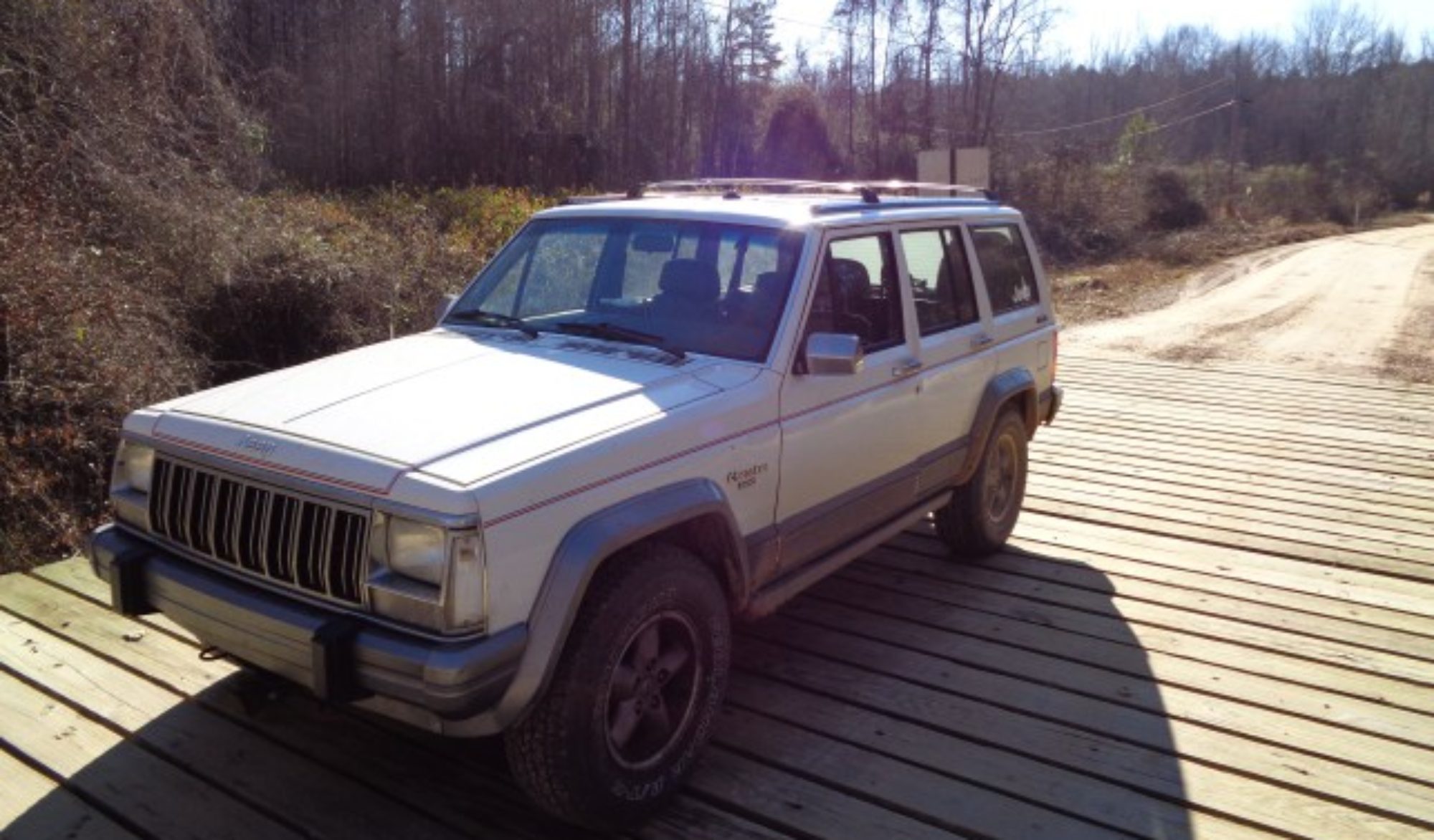
Curing a soft brake pedal on a Jeep Cherokee

Curing a soft brake pedal on a Jeep Cherokee

A soft brake pedal on a Jeep Cherokee can be very unnerving. The brakes are not exceptionally great on a Jeep Cherokee to begin with so when they are not working well, they can be downright scary.

The first place to look on a Cherokee is the adjustment of the rear drum brakes. If the shoes not adjusted right, then the pedal travel required to take up the slack will be enough to make the pedal feel soft.

To adjust the shoes, remove the rubber plug in the backing plate. Use a screwdriver or better yet a brake spoon to turn the spiked wheel. Turn it down to tighten the shoes. I usually tighten them until there is noticeable drag when turning the tire.

If the adjuster does not click when you turn the wheel, then the auto adjuster is likely not installed correctly. I see this problem often. The auto adjuster is operated by a cable the moves the adjuster wheel when the brakes are applied in reverse. The cable is routed over a small metal pivot point. Often the metal piece is not installed correctly under the spring and will allow slack in the cable. To fix, simply remove the spring and reposition the pivot plate in the hole and reinstall the spring. Just make sure the plate stays in place as you reattach the spring. That is the tricky part.

Also, if exposed to road salt, the adjuster screw may seize. Free it up with a rust dissolving oil like PB blaster or ATF. Coat it with grease when re installing to help prevent it seizing.

If the rear brakes are adjusted properly ands the pedal is still soft, you may have air in the lines or a leak. Check the rear wheel cylinders for evidence of leaks. Look for traces of fluid inside the brake drum. In the front, look for fluid around the calipers.

If you still have a soft pedal then you will need to bleed the brake system to purge any air. Air can get in if the master cylinder has ever run dry or if a brake line has been removed for any reason.

I prefer to use a pressure bleed system to bleed the brakes. I find it gets air out faster and I can do it without an assistant. I don’t like using vacuum bleeders because I have found that they can pull air in past aging wheel cylinder seals. If the seal are new this wont be a problem but old ones can allow in air during a vacuum bleed even if they don’t leak fluid out. The old “pump and bleed” method works if you have an assistant but is slower than a pressure bleed.

One last are to look at if you continue to have a soft pedal after checking all of the above is the front brake calipers themselves. Some Jeep calipers use a phenolic piston. The plastic in the piston can break down with heat and start to crumble. If the piston is breaking it may flake off a little each time the pedal is mashed.

Often the brake pedal firmness fades slowly and you get accustomed to it. Once a firm pedal is restored, you may be surprised at how well your Jeep stops and how easy the brakes are to modulate.

Jeep Cherokee Check Engine Light Codes.

Jeep Cherokee Check Engine Light Codes.

On the 91 to 96 Jeep Cherokees the ECU codes are accessible by watching the Check engine light blink on the dash. You cycle the key on and off three times leaving it on but not starting the Jeep. The codes will begin to flash on the dash light. Count the flashes and note the pause between flashes. For example the first code will usually be a 12. The light will blink once then pause and then blink twice more. The last code is always a 55.

Below are the instructions from the FSM on how to get the codes. Below that is the chart of what the codes mean. This chart was taken from the 94 FSM but all the HO engines will be similar.

ACCESSING DIAGNOSTIC TROUBLE CODES
A stored Diagnostic Trouble Code (DTC) can be displayed by cycling the ignition key On-Off-On-Off-On within three seconds and observing the Malfunction Indicator Lamp. This lamp was formerly referred to as the Check Engine Lamp. The lamp is located on the instrument panel.

11 * No Crank Reference Signal at PCM No crank reference signal detected during engine cranking.
12 * Battery Disconnect Direct battery input to PCM was disconnected within the last 50 Key-on cycles.
13 ** No Change in MAP From Start to Run No difference recognized between the engine MAP reading and the barometric (atmospheric) pressure reading at start-up.
14 ** MAP Sensor Voltage MAP sensor input below minimum acceptable voltage.
or
MAP sensor input above maximum acceptable voltage.
15 ** No Vehicle Speed Sensor Signal No vehicle distance (speed) sensor signal detected during road load conditions.
17 * Engine is Cold Too Long Engine coolant temperature remains below normal operating temperatures during vehicle travel (thermostat).
21 ** O2S Stays at Center Neither rich nor lean condition detected from the oxygen sensor input.
or
O2S Shorted to Voltage Oxygen sensor input voltage maintained above the normal operating range.
22 ** ECT Sensor Voltage Engine coolant temperature sensor input above maximum acceptable voltage.
or
Engine coolant temperature sensor input below minimum acceptable voltage.
23 ** Intake Air Temp Sensor
Voltage Low Intake air temperature sensor input below the minimum acceptable voltage.
or
Intake air temperature sensor input above the maximum acceptable voltage.
24 ** Throttle Position Sensor
Voltage Throttle position sensor input above the maximum acceptable voltage.
or
Throttle position sensor input below the minimum acceptable voltage.
25 ** Idle Air Control Motor
Circuits A shorted condition detected in one or more of the idle air control motor circuits.
27 * Injector Control Circuit Injector output driver does not respond properly to the control signal.
33 * A/C Clutch Relay Circuit An open or shorted condition detected in the A/C clutch relay circuit.
34 * Speed Control Solenoid
Circuits An open or shorted condition detected in the Speed Control vacuum or vent solenoid circuits.
or
Speed Control Switch Always Low
Speed Control switch input below the minimum acceptable voltage.
or
Speed Control Switch Always High
Speed Control switch input above the maximum acceptable voltage
35 * Rad Fan Control Relay
Circuits An open or shorted condition detected in the radiator fan relay circuit.

41 ** Generator Field Not
Switching Properly An open or shorted condition detected in the generator field control circuit
42 * Auto Shutdown Relay
Control Circuit An open or shorted condition detected in the auto shutdown relay circuit.
44 * Battery Temp Sensor
Volts out of Limit An open or shorted condition exists in the engine coolant temperature sensor circuit or a problem exists in the PCM’s battery temperature voltage circuit.
46 ** Charging System Voltage
Too High Battery voltage sense input above target charging voltage during engine
Operation
47 ** Charging System Voltage
Too Low Battery voltage sense input below target charging during engine operation.
Also, no significant change detected in battery voltage during active test of generator output.
51 ** O2S Signal Stays Below Center (Lean) Oxygen sensor signal input indicates lean air/fuel ratio condition during engine operation.
52 ** O2S Signal Stays Above Center (Rich) Oxygen sensor signal input indicates rich air/fuel ratio condition during
engine operation
53 * Internal PCM Failure
Or
PCM Failure SPI Communications PCM Internal fault condition detected.
or
PCM Internal fault condition detected.
54 * No Cam Sync Signal at
PCM No fuel sync (camshaft signal) detected during engine cranking.

55 . N/A Completion of diagnostic trouble code display on the Malfunction Indicator Lamp (Check Engine Lamp).
62 * PCM Failure SPI miles not stored Unsuccessful attempt to update SPI miles in the PCM EEPROM.

63 * PCM Failure EEPROM
Write Denied Unsuccessful attempt to write to an EEPROM location by the PCM.

* Check Engine Lamp will not illuminate at all times if this Diagnostic Trouble Code was recorded. Cycle Ignition key as described in manual and observe code flashed by Check Engine lamp.
** Check Engine Lamp will illuminate during engine operation if this Diagnostic Trouble Code was recorded.

Replacing the transmission filter on a Cadillac Catera

Replacing the transmission filter on a Cadillac Catera

A friend has a 1997 Cadillac Catera that he really enjoys driving despite its unreliable service history. Recently the car refused to move indicating a transmission problem. He son had suggested trying a filter and fluid swap first and had planned to do the work in his driveway. However, he soon found that the Catera’s 4L30E transmission is a strange animal. It does not have a dipstick to check the fluid or even an easy way to add fluid.

The fluid is checked and added through a hole in the side of the transmission pan. The car has to be level and the engine running to check the fluid. To make matters worse, the exhaust pipe passes just inches away from the filler plug. He decided to let me do the job on my lift.

I began by lifting the car and removing the plug in the side of the pan. Fluid gushed out indication that the level is higher with the engine off than when it is running. I realized it was going to be a challenge to refill it when I was done.

I then dropped the pan by removing the 10mm headed bolts. The pan separated easily and cleanly. I poured the remaining fluid into the oil catch can. The fluid did not smell burnt or look too dark.

I noticed right away however that the magnet in the pan was thick with metal particles. I took a cell phone photo and sent it to the owner. I then cleaned up the magnet and pan.

The filter is held in place by three long bolts that surprised me by having ½ inch heads rather than the 13mm I was expecting. Wikipedia says the transmission for these cars is built in France.

There were more metal flakes on top of the filter making me think the transmission is heavily damaged. However we decided to button it back up with the new filter and fluid just to see.

I tried using a long tube and a funnel but filling by gravity just took too long. I rigged up a pump using a pressure bottle and a tube attached to it. This sped up transferring the fluid greatly. It still took me an hour an a half to get all the fluid in. I had to climb a ladder to start the engine once the fluid filled the pan with it off. I was able to get all the fluid in before the exhaust got too hot.

I dropped it down and took it for a test drive. I noticed right away that the jerky motion it had when first changing directions was gone. The car now started off smoothly just like a Cadillac should. I took it out on the road and it shifted smoothly through all its gears. I was really surprised that just changing the filter cured it.

I still need to recheck the fluid level now that it has had a chance to circulate the fluid, but it looks like it will be able to go a few more miles. I told him to start shopping for a transmission just in case.

[phpbay]catera transmission, 10[/phpbay]