Reattaching a Rear View Mirror

Reattaching a Rear View Mirror

When my mirror fell off while racing the Rallye de Parris, I causally said to my co driver, “Whats a behind me is not important.” The video shows me tossing the mirror to the back and it hitting the camera lens. The remainder of the video is much better without the big mirror in the way however.

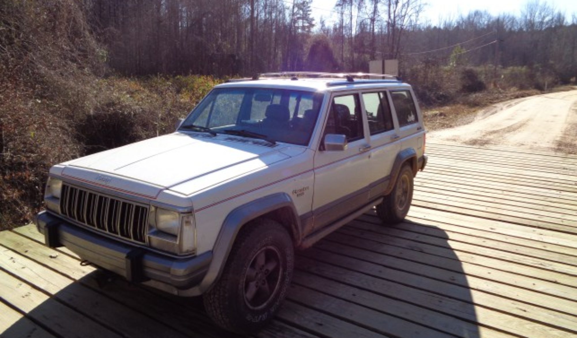
The mirror was tossed into the tool box and forgotten. Now that the Jeep is used for Off Roading, it is nice to see what is going on behind me. I have mounted a nice big mirror on the fender for when the doors are off. But not having the center mirror makes it hard to see the rig behind me at times.

I found the mirror, but the metal dot that glues to the windshield was missing. I found one at Advance Auto that had glue already on it. I had to rim it a but to fit the Jeep mirror. I just used my grinder to trim it down to fit.

To locate the proper place for the bracket, I measured the location on my street Jeep. I made a small x on the outside of the glass with a marker. I then used brake cleaner to clean the inside of the glass.

I pulled the backing off the adhesive and pressed the dot in place over the mark in the glass. i held it a second or two to make sure it bonded. I then cleaned the mark from the outside of the glass.

I let the glue set for a few minutes before slipping the mirror over metal dot. I tightened the set screw and adjusted the mirror so I could see out the back.

I suspect it will take me a while to get used to it being there again. But it will be really nice one the drive to the trail head and when keeping up with the rig behind me on the trails.

Welding Safety

Welding Safety

I grew up around a welding shop. My grandfather was a welder and so was my father. A lot of welding safety has just been second nature for me. However, I have recently picked up welding as a hobby myself and I have noticed that munch of the welding safety advice in the books is overly complicated.

So here are some simple tips for staying safe while enjoying making stuff with steel. This list is by no means exhaustive. I am sure there are many different ways you can get hurt while welding but these basic steps will keep you from the most common hazards.

The most obvious hazard of welding is the light from the arc. Not only is the arc flash hazardous to the operator but to those in the area. A welding hood is the common protection. The shade of the lens needs to be around a 10 so that the welder can see the weld puddle and still be protected from the light. I use a 9 on my MIG welder. Higher amperage arcs may need darker lenses.

The light contains a lot of UV radiation so skin protection is needed as well. The welding hood should cover the face and neck. UV resistant clothes need to be worn over the chest and arms. I have a small tanned V on my chest from forgetting to button the top button on my welding shirt. One last note on UV radiation – it is hard on cotton fabric. Be warned that your favorite pair of jeans can easily be reduced to shreds by UV radiation even if you avoid burning a hole in them.

The second most obvious hazard is the heat. Hot molten metal tends to fly out in all directions from the weld. Long leather gloves are the most common way to protect the hands and wrists. The parts will also be hot just after welding so the leather gloves help in handling the hot parts. Just remember that the heat will deteriorate the gloves over time so don’t handle hot parts more than necessary.

Foot protection is helpful as well. Cloth shoes and laces can catch fire due to molten metal falling on them. High top boots are recommended to keep hot blobs off your ankles.

Hot work also adds the danger of starting a fire. Fire protection needs to be considered for all welding and burning. See http://ezinearticles.com/?Hot-Work-Safety&id=5890147 for more info.

One less obvious hazard is handling compressed gas bottles on a MIG welder. While the gas is inert and non flammable, it still has a lot of stored energy that can be hazardous if the cylinder is dropped and the valve is damaged. If discharged in a confined space the Argon or CO2 can displace the oxygen in the air. So, make sure cylinders are properly secured in use and in transit. Make sure the cap is in place anytime the cylinder is moved.

Be aware of hazards that can be created during the welding process as well. When welding on a vessel like a drum or a tank, make sure the inside space has been purged of any flammable liquids or gases than could have been trapped inside. When welding on a vehicle, check the area near or behind the welding area. Ensure that fuel or brake lines will not be damaged by the heat.

One less common but very painful hazard occurs when welding zinc coated or galvanized metals. Know as metal poisoning, breathing the vaporized zinc will cause a severe headache. The old-time remedy is to drink milk on the theory that the calcium will displace the zinc in the body tissues. The condition can be prevented by having adequate ventilation when welding or by using respiratory protection.

Welding provides a great escape for the worries of the day, as it required total focus for me to make and maintain a quality bead. Following basic safety precautions will ensure that welding is done safely and enjoyably.

Second Prototype Gas Tank Skid Plate

Second Prototype Gas Tank Skid Plate

I liked the skid plate I fabricated for Jennifer’s XJ so well that I decided to make one for my Jeep. I did however make a few changes in the design. I did not like the way I bolted hers in place by tapping into the thin metal frame rails. One of the bolts stripped out and had to be replaced with another one near by. I have bought rivet nuts to strengthen it next time it is taken off her Jeep.

For mine, I decided to fabricate a bolt strip to insert inside the frame rail. To make the strip, I first had to remove the rear bumper. This is easy on my off road Jeep due to the way the custom pipe bumper is made. I also took this opportunity to remove two broken off bolts in the bumper mounting surface.

The first one was accessible from behind the bolt hole so I simply clamped vise grips onto the end of the bolt and turned it out the back. I did have to use some heat and penetrating oil to get it to turn but one it did, it came right out the back.

The second bolt was at the top and I could not access it with vise grips. I could however spray penetrating oil on the exposed part. I first tried cutting a slot in the bolt and turning it with a screw driver. That did not work at all. Next I made a deeper slot and tried my impact driver. I was able to turn the bolt about half a turn before it stopped again. Even heating it cherry red did not help.

Next I took a nut and welded it to the broken off bolt. I used my flux core wire welder to make the weld. The bolt came out relatively easily with the nut welded to the top.

I measured for the two holes that were already in the frame rails. I then marked an approximate location for the third bolt. I drilled the holes in the angle used for the mounting bracket. I then made a strip of flat bar with the same hole spacing using angle as a jig. I then welded in two bolts into the holes that lined up with the two in the frame rail. I used a magnet to slide the strip into place and temporarily bolted the angle in place. I then drilled through the hole in the bracket into the frame rail. I then removed both parts and welded in the third bolt.

I repeated the procedure for the other side. I had to open the hole at the rear of the Jeep slightly to get the strip inside. I used a cut off wheel to make two vertical slits and then bent the metal out to open the hole enough to get the bolt strip in. Fishing it under the gas filler section was challenging but it worked.

With the mounting points fabricated, I used the template from the first skid plate to lay out the side pates. I extended them about a quarter of an inch to give a little extra clearance when installing the plate. The bottom plate ended up about a half inch wider. I am not sure how that happened. However, I like the extra clearance on the side of the tank.

Another change I decided to make was the exhaust hanger. Jennifer’s uses the exhaust hanger bolts as mounting bolts. However, these proved extremely difficult to install when mounting the skid plate. For mine I fabricated studs and welded them to the mounting angle. Now I can simply slip the hanger over the studs and install two nuts. I expect this to be much easier.

I currently have the sides and the bottom tack welded together. My next step is to remove the assembly from the Jeep and complete the welds. I picked up a new roll of wire for the welder today.

UPDATE: Last night I took it down and did the final welding. I finished off the spool of wire that came on my MIG so I had to learn how to change wire in the middle of the welding process. I ground down the edge and now it is ready to be sanded for paint.

Skid plate bolts

frame holes opened up

mounting bolts for skid plate

studs for the exhaust hanger

finished gas tank skid plate

UPDATE 2: I added a small lip at the front edge that adds a lot of strength to the plate. I also sanded it down and painted it black.

Exhaust hanger detail

Exhaust in place

Filler cover detail

Jeep Cherokee Power Steering Hose Replacement

Jeep Cherokee Power Steering Hose Replacement

I have replaced several power steering hoses on various Jeep Cherokees. It has gotten to be a pretty straight forward job. See this previous post on how to replace a power steering hose.

Janice’s 1999 Cherokee had been emitting a puff of smoke each time she turned her XJ to full lock. Although there was little sign of a leak on the hose, our experience with the Green Jeep catching fire due to a power steering hose leak made me extra cautious.

I got a new hose and then pulled the electric fan and the air box to make room. I tried using the various 18mm wrenches I had to get the hose loose from the steering box. I have always been successful in the past using an open end wrench. However, this one refused to budge.

I picked up a set of crow foot flare nut wrenches from my local NAPA store. They have a great set of tools in a nice case for around $20. Unfortunately I forgot that the bottom is an 18mm and the top is a 5/8 inch. I bought only the SAE set. The store was closed for the holiday by the time I figured out I also need the metric set.

Jennifer rescued me by searching until she found a set at O’Reilly’s. It is still a nice set for about the same price as the NAPA set but does not have the nice case.

I used the 18 metric crow foot flare nut wrench to break loose the lower line. It took a lot of torque but it eventually broke free. Janice and Jennifer were able to finish taking it out using the 18mm stubby wrench.

I used the 5/8 crow foot to pop loose the upper hose. It was not nearly as tight. I showed them how to put on the O rings on each end of the hose and let them get the lines threaded into place. The lower one always seems to be difficult and takes some patience to get it started.

After the new line was installed, I had them add some fluid and jack up the front of the Jeep. They turned the wheel from lock to lock to bleed the air out of the line. After that, they started the engine and repeated the process.

Once most of the air was out, she turned the wheel to one of the locks and listened for the pressure relief to open. There was a noticeable change in sound as the last of the air purged.

I rechecked the level of fluid in the power steering reservoir and checked for leaks again. Now we all feel much safer driving the Jeep.


Powercraft Power Steering Pressure Hose – 80290

Powercraft Power Steering Pressure Hose - 80290

How to Replace Rear Brake Shoes on a Jeep Cherokee

How to Replace Rear Brake Shoes on a Jeep Cherokee

While many people swap in disk brakes, the rear drum brakes on the Jeep Cherokee work pretty well when they work correctly. They self adjust each time they are applied in reverse. The shoes will generally last at least 100,000 miles.

Begin by lifting the Jeep and removing the rear wheel. Next remove the brake drum. If it has never been off before, there will be one or two spring clips on the lug studs. Grab these with pliers and break them away or try to unscrew them from the studs.

Pull on the drum to remove it. If it hangs on the shoes, remove the rubber cap on the backing plate and use a brake spoon to release some of the tension on the shoes. Rotate the adjuster up to release.

If the drum hangs on the hub, try hitting the face of the drum with a hammer. This will often break loose the rust weld at the center. Penetrating oil may help as well. In severe cases you may need a drum removal tool.

Once the drum is removed, inspect the brakes. There should be two overlapping springs at the top, an adjuster cable running from the top to the bottom of the rear shoe, retaining springs on each shoe and a smaller spring connecting the two shoes at the bottom.

The adjusted lever should lightly contact the wheel on the adjuster screw. The screw should turn freely when the adjuster lever is moved away from it.

If any of the springs as broken or missing, you will need a spring kit with the new shoes. If the cable or the adjuster is not working properly, you will also need a small parts kit.

To remove the shoes, I start with the retaining clips. Press in on the cup using either a brake tool or a pair of vise grips. Reach behind the backing plate and rotate the pin until it lines up with the slot in the cup. Release the spring to separate it from the pin. Use the same procedure on the other shoe.

Next remove the two large springs at the top. Use either a spring tool or a pair of vise grips to release one spring at a time. Note that the spring on the rear shoe also holds the cable pivot in place. Note the arrangement so you can put it back later.

The two shoes can now be slipped down around the axle and the lower spring can be removed as well as the adjuster. Pay attention to how the hand brake lever engages the rear shoe so you can put that back later. Also note the orientation of the adjuster screw. I like to lay all the parts out on the floor in a sort of exploded view so that I can reference it upon reassembly.

The mounting pin for the new shoes will likely not be installed. To put it in, note which side it is mounted on the old shoe. Use a vise to press the pin into the hole in the new shoe.

Put a small dab of grease on the backing plate in the places where the shoes contact. Also inspect the wheel cylinder and replace it as necessary before installing the new shoes.

Set a shoe in place and set the retaining spring over the hole. Insert the pin from the rear and align it with the slot in the cup. Compress the spring and rotate the pin to lock into the cup. Then release the spring to hold it in place. Do the same with other shoe. Note that the front and rear shoes are different. Make sure you have them in the correct place. Also make sure they properly engage the wheel cylinder. Slip the bar in place between the shoes in the upper slots.

Put the loop of the cable over the anchor pin. Hook the spring for the front shoe in the hole and use a spring tool to hook the spring over the anchor pin. Carefully place the cable pivot into the hole in the rear shoe. Hook the spring to hold it in place. Use the tool to secure the spring to the anchor. Inspect the pivot to make sure it is properly engage in the hole and is flat against the shoe. Adjust as needed.

Use pliers to install the lower spring between the shoes. Rotate the adjuster screw to fully closed. Stretch the spring and slip the adjuster screw in place between the screws. Clip the adjuster lever to the pin in the rear shoe. Install the spring on the lever. Tip the lever up and attach the adjuster cable making sure it is routed properly around the pivot.

When properly fitted, the lever will be against the cog wheel o the screw. It if hangs above or below the wheel, adjust the pivot under the spring. Adjust the screw until the drum will go on with just a slight drag. Install the drum and make a final adjustment of the screw through the access hole in the backing plate.

Repeat the procedure on the opposite side. Keep in mind however that the other side is reversed and even the screw threads on the adjuster screw are opposite.