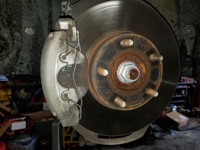
Fabricating a Gas Tank Skid Plate for a Jeep Cherokee

January 2nd, 2012

The fuel tank on Jennifer’s XJ has taken quite a beating from off road driving. In fact the fuel pump pickup is no longer the lowest point in the tank making the effective size of the tank much smaller than its original 20 gallons. She will need a new tank to cure this problem but in the mean time, I decided to fabricate a skid plate to prevent further damage and to be ready when she can get a replacement tank.

I began by making a mock up out of foam construction board. The pieces I had had once been a sales display. It provided several large sheets of ¼” poster board with a foam liner. The material is stiff, lightweight and easy to cut and draw on.

I looked at several skid plates commercially available and I did not like the way they mounted. I wanted something that attached to the unibody frame rails one either side of the tank. Of all the ones I looked at, only the Mopar plate mounted like that.

I began with two pieces of 3x3x1/4 angle. I cut them to extend from the front of the trailer hitch to the front of the tank. I shaped the upper flange to match the shape or the curved frame rail section. I drilled holes in the angle face and then made corresponding holes in the Jeep. I tapped the sheet metal for 5/16 bolts. I used the existing exhaust hanger bolts on the passenger side as well.

Using the template I made from foam, I cut two side plates form 3/16 scrap. These extend the angle down to level with the lowest point on the tank. They are angle d at the rear so that I could mount a plate angled up behind the gas tank to protect the rear of the tank and not take away departure angle. I ended the rear late below the trailer hitch cross bar.

I then welded the extensions to the vertical parts of the mounting angle. I bolted the side pate to the Jeep temporarily and confirmed the measurements of the two main plates. I put one large plate under the main part of the tank and second plate going up at an angle at the rear of the tank. The fabricated angle between the two plates adds a lot of strength.

I tack welded the bottom plate to the side plates. I then took the assembly down and finished welding the bottom to the sides. I then welded the back plate to the assembly. I made a series of short welds along the long seam to avoid warping the metal.

Once the welds were finished I ground the edges smooth and painted it black.

Putting the entire assembly back up took some help as it was now too heavy to balance on one hand. Jennifer assisted me by balancing it on the under lift stand. She also helped move the exhaust pie out of the way while I started the bolts. Only one of the 5/16 – 18 bolts stripped in the thin frame rail. The others tightened down well. I drilled and tapped a new hole to replace the one that stripped.

I plan to replace the tapped holes with nut rivets in the future if these do not hold. The skid plate is very sturdy and neatens up the appearance of the rear of the Jeep. I think I will have to make another one for my Jeep now.

How to Replace the Rear Brake Hose on a Jeep Cherokee

December 28th, 2011

How to Replace the Rear Brake Hose on a Jeep Cherokee

The brake fluid for the rear brakes on a Jeep Cherokee passes through a metal line from the master cylinder to a point above the rear axle. There it makes it way to the axle by a rubber hose. This hose can be damaged if the axle over travels either by having longer shocks or by having the shocks disconnected.

To disconnect the hose, first remove the metal line from the joint. The joint is right above the sway bar if you still have one. Use a 3/8 line breaking wrench. It may be necessary to heat the joint to break it free if it is rusted. Be careful not to twist the metal line as it goes al the way to the master cylinder and can be difficult to replace if you damage it.

Once the metal line is loose, remove the retaining clip. If the swap bar is still in place access is difficult. If the bracket is rusted, the impact of a hammer will be needed to break it free. Some penetrating oil may help as well. Once the clip moves some, it can be pried off with a screw driver.

Once the clip is removed, pull the line out of the hex opening in the bracket. Next, remove the two metal lines that go from the junction block to either side of the axle. These also require a 3/8 line breaking wrench.

Once the two lines are disconnected, remove the bolt that holds the junction block to the axle. On the later models this bolt is hollow and is also the vent. You can leave the vent tube attached and just let it wind up as you unscrew it. The bolt uses a 9/16 wrench.

Clean the mounting surface and set the curved side of the new block against the axle. Attach it with the bolt. Carefully align the two metal lines and attach then to the block.

If the vehicle is lifted by the body, it may be necessary to raise the axle slightly so that the new hose will have some slack for the next step. I use my under lift screw jack to lift it a couple of inches.

Fit the end of the hose in the hex hole in the bracket. Make sure it is seated against the clip on the hose. Slip the C clip in the slot and tap it in place. You can now release the axle to make sure the hose is not too tight at full droop. If the shock does not limit the travel enough, you may need to limit the travel with a strap or get a longer hose.

Reconnect the metal line to the hose fitting. Refill the master cylinder and bleed the brakes before driving. It will take quite a bit of fluid passed through to purge all the air from the new line.

How to Replace Rear Brake Shoes on a Jeep Cherokee

December 27th, 2011

How to Replace Rear Brake Shoes on a Jeep Cherokee

While many people swap in disk brakes, the rear drum brakes on the Jeep Cherokee work pretty well when they work correctly. They self adjust each time they are applied in reverse. The shoes will generally last at least 100,000 miles.

Begin by lifting the Jeep and removing the rear wheel. Next remove the brake drum. If it has never been off before, there will be one or two spring clips on the lug studs. Grab these with pliers and break them away or try to unscrew them from the studs.

Pull on the drum to remove it. If it hangs on the shoes, remove the rubber cap on the backing plate and use a brake spoon to release some of the tension on the shoes. Rotate the adjuster up to release.

If the drum hangs on the hub, try hitting the face of the drum with a hammer. This will often break loose the rust weld at the center. Penetrating oil may help as well. In severe cases you may need a drum removal tool.

Once the drum is removed, inspect the brakes. There should be two overlapping springs at the top, an adjuster cable running from the top to the bottom of the rear shoe, retaining springs on each shoe and a smaller spring connecting the two shoes at the bottom.

The adjusted lever should lightly contact the wheel on the adjuster screw. The screw should turn freely when the adjuster lever is moved away from it.

If any of the springs as broken or missing, you will need a spring kit with the new shoes. If the cable or the adjuster is not working properly, you will also need a small parts kit.

To remove the shoes, I start with the retaining clips. Press in on the cup using either a brake tool or a pair of vise grips. Reach behind the backing plate and rotate the pin until it lines up with the slot in the cup. Release the spring to separate it from the pin. Use the same procedure on the other shoe.

Next remove the two large springs at the top. Use either a spring tool or a pair of vise grips to release one spring at a time. Note that the spring on the rear shoe also holds the cable pivot in place. Note the arrangement so you can put it back later.

The two shoes can now be slipped down around the axle and the lower spring can be removed as well as the adjuster. Pay attention to how the hand brake lever engages the rear shoe so you can put that back later. Also note the orientation of the adjuster screw. I like to lay all the parts out on the floor in a sort of exploded view so that I can reference it upon reassembly.

The mounting pin for the new shoes will likely not be installed. To put it in, note which side it is mounted on the old shoe. Use a vise to press the pin into the hole in the new shoe.

Put a small dab of grease on the backing plate in the places where the shoes contact. Also inspect the wheel cylinder and replace it as necessary before installing the new shoes.

Set a shoe in place and set the retaining spring over the hole. Insert the pin from the rear and align it with the slot in the cup. Compress the spring and rotate the pin to lock into the cup. Then release the spring to hold it in place. Do the same with other shoe. Note that the front and rear shoes are different. Make sure you have them in the correct place. Also make sure they properly engage the wheel cylinder. Slip the bar in place between the shoes in the upper slots.

Put the loop of the cable over the anchor pin. Hook the spring for the front shoe in the hole and use a spring tool to hook the spring over the anchor pin. Carefully place the cable pivot into the hole in the rear shoe. Hook the spring to hold it in place. Use the tool to secure the spring to the anchor. Inspect the pivot to make sure it is properly engage in the hole and is flat against the shoe. Adjust as needed.

Use pliers to install the lower spring between the shoes. Rotate the adjuster screw to fully closed. Stretch the spring and slip the adjuster screw in place between the screws. Clip the adjuster lever to the pin in the rear shoe. Install the spring on the lever. Tip the lever up and attach the adjuster cable making sure it is routed properly around the pivot.

When properly fitted, the lever will be against the cog wheel o the screw. It if hangs above or below the wheel, adjust the pivot under the spring. Adjust the screw until the drum will go on with just a slight drag. Install the drum and make a final adjustment of the screw through the access hole in the backing plate.

Repeat the procedure on the opposite side. Keep in mind however that the other side is reversed and even the screw threads on the adjuster screw are opposite.

How to Replace the Transmission in a Cadillac Catera.

December 23rd, 2011

How to Replace the Transmission in a Cadillac Catera.

The Cadillac Catera was designed a sport grand touring car. It is actually an Opel Omega built in Germany. When it was introduced, the automotive magazines sang its praises loudly. The car drives and handles well. However, they have proven to be rather high maintenance and unreliable. Also, parts are hard to get and they are expensive.

The transmission is a GM 4L30E. This same transmission is used in BMW’s and Isuzu Troopers. I found some useful information in some of the Trooper forums.

The owner of this particular Catera found a replacement transmission on ebay. I had it delivered to my office parking lot. We swapped it on to my little utility trailer in the parking lot rather than having the truck negotiate the long gravel driveway to my shop.

With the car on the lift and the battery disconnected, I began by draining the fluid. Fluid is added through a hole in the side of the pan. There is no dipstick or filler tube like on other GM transmissions. I only drained the amount that comes out when the engine is off. The level in the pan is lower when the transmission pump is running. For this reason, the transmission fluid level must be checked with the engine running. Which is interesting considering the exhaust pipe runs just a couple of inches from the fill hole.

To release the torque converter from the pressure plate, I removed the rubber plug from the bottom of the bell housing. I used a long screwdriver to slowly rotate the flex plate until a bolt was visible through the front hole. An assistant with small fingers was helpful in removing the bolts through the access hole. There are six bolts that hold the torque converter to the flex plate. They all had 15mm heads.

I next disconnected the drive shaft at the coupling. I should have dropped the exhaust pipes at this point. It would have made removing the oil cooling lines much easier. Next I disconnected the electrical connectors and the oxygen sensors and removed the exhaust pipes. Be careful with the sealing rings at the front as they are very expensive from the GM dealer if you damage one. You can likely get them cheaper at a muffler shop but I was able to reuse the ones on this car.

With the pipes out of the way, disconnect the shift linkage and anything else that might be connected. You may have to cut some wire ties on the wiring harness. Next, support the transmission on a jack and remove the cross member. The transmission mount was broken on this car so the cross member fell off when the bolts to the body were removed. The body bolts had locktite on them and were very difficult to remove.

Two of the main transmission bolts come in from the front of the engine and the rest come in from the transmission side. They all had 19mm heads. There are also four small bolts that hold the bottom of the bell housing.

I removed all the bolts and carefully slid the transmission back off the dowels and let the converter nose slip out of the crank. Then I lowered it out form under the car.

I set the two transmissions side by side on the floor and made sure everything was a match. All the sensors were in place on the replacement transmission so I did not have to move any over.

I then secured the transmission on the jack and set it level as that was how the engine was sitting. The sticker on the replacement transmission warned that the front seal needed to be replaced. I did not see any evidence of leakage but I pulled the torque converter any way to see how the seal looked. Sure enough, there was a visible worn spot on the seal.

The owner picked up on at Auto Zone that did not fit. He tried to get one form the Cadillac dealer but it was going to take two weeks. We found one on ebay but I decide to try one from Advance auto. That seal was made different but fit fine. The original seal has three bolts that hold it in place. The instructions say not to drive the seal in but to use the bolts to pull it down to a seat. The replacement seal from Advance did not have the three bolt holes so I had no choice but to drive it in. I did so carefully.

I had a lot of trouble getting the torque converter indexed back on the pump drive splines. I thought I had it once but when I went to set the transmission in place, it contacted the flex plate way too soon. I had to set it back down and try again. After much spinning of the torque converter, it finally dropped into place on the cogs and then there was plenty of room.

I made sure the transmission was lined up with the engine and carefully slid it into place. Everything slid into place easily. However I took my time and made sure that the bolts drew the transmission up evenly.

Ideally you would spin the torque converter a few times to make sure it is centered in the crank before bolting it to the flex plate. However, due to the design of the bell housing, all I could do was rock it back and forth a few times. I was glad I had pre aligned one of the tabs on the converter with a hole in the flex plate because it is very difficult to turn the torque converter through the tiny access hole.

I use a magnet and a small fingered assistant to work the bolts into place. Between bolts, I again used my long screwdriver to slowly rotate the flex plate to the next position. Once they were all in, I spun it all around one more time and torqued each one down tight.

Next I reconnected the wires and the shift linkage. I then reconnected the cooling lines being careful with copper washers on the rear banjo fitting. I fitted a new mount and reattached the cross member and exhaust hanger. There is a helpful arrow on the cross member to show which way is the front.

With all the bolts in place, I then reconnected the drive shaft. I had to use a soft hammer to get the shaft to slip over the output shaft of the transmission. I did not wan tot try to pull it down with the coupler. The local dealer wanted $220 for the coupler, so don’t damage it.

I set eh left side exhaust pipe in place and reconnected the oxygen sensors. I then dropped the oil pan and installed anew filter and gasket. It was much easier to do this job under the car than with the transmission on the floor. I reinstalled the pan and filled it with fluid. I then put up the other exhaust pipe which limits access to the fill hole.

To fill the entire transmission, the pump must be turning. That means that the engine must be running.

Based on advice from a friend, I built a device to quickly put fluid in the transmission. I used a length of ½ inch clear tubing and a gallon transmission fluid jug. I drilled a ½ hole in the cap of the bottle and slipped the hose inside and down to the bottom. I used my heat gun to help straighten the hose. I then drilled a 3/8 hole near the handle of the jug. I put fluid in the jug and slipped the hose in the fill hole. I then used my air blow gun to pressurize the jug and force the fluid up into the transmission. A quart of fluid will transfer in seconds so be careful if you use this method.

Once the transmission was filled, I plugged the hole and lowered the car. I shifted it into all the gears and drove it forward and backwards. I could hear the pump whining so I knew it still needed more fluid. I picked it back up and filled it again. It seemed to stay full after having moved all the solenoids by selecting all the gears and moving the car.

I gave it a test drive and brought it back and checked for leaks. Finding none, I drove it back to the happy owner.

Hacking with Sugru

December 20th, 2011

Hacking with Sugru

I have been reading about Sugru on several websites. I finally decided to order some and see what all the fuss is about.

I looked through the various bright colors and decided that black was really the only color I could see my self using for the projects I had in mind. It took some looking but I finally found where to order single color packs on the website. I entered my info and waited. My envelope arrived a few days alter and I was anxious to try out a packet.

I was at first surprised at how small the packets were. Somehow I had expected more volume for $15 but if it lives up to its reputation, it will be worth the price of admission.

For my first hack, as they call it, I decided to repair my broken key chain flash drive. It get s a lot of use and abuse and the case has been held together with tape for a while. More and more bits of plastic crumble off it each day. The exposed circuit board was beginning to worry me so it was an ideal test for my first Sugru hack.

I realized that about half a pack was all I was going to need for the repair. I did not want to waste the rest of the pack so I looked around for something else to test it on. I found a 2M radio that had an exposed wire at the power cord. Electrical tape keeps coming of the joint so I decided to try the Sugru.

For the thumb drive, I had to do a little prep work. The drive slips into a cover that is the key chain part. I needed to make sure the Sugru covered the damaged area but did not interfere with slipping it into the case. I read in the instructions that soap is a release agent. So I coated the case with dish soap and then molded the repair blob around the broken end of the drive. While it was still moldable, I slipped it into the cover. This made the Sugur form around the cover edge. I molded it in to the shape I wanted and let it set hoping it would really release for the cover.

The remaining Sugru, I molded into a blob around the wire side of the connector on the radio. I had a lot more confidence in this repair as I was able to work the putty between the wires and give it some mechanical grip as well as its adhesive powers.

After letting both tests set overnight I am pleased with the results in both cases. The thumb drive stuck a little in the cover but I was able to pull it out with a little force. It looks much better than the tape and exposed circuits. I think it is well protected now and should last a while.

The radio wire repair looks nice too. The joint is flexible and is much neater than having electrical tape wrapped around it. I am looking forward to hacking more things with Sugru.