How to disable the steering wheel lock on a race car.

How to disable the steering wheel lock on a race car.


On our Toyota Celica we went to the trouble to drill out the security screws and remove the lock cylinder from the steering column.  Then I used a cut off wheel to shorten the locking pin until it no longer engaged the shaft.

On our Sentra Race car, however I tried a tip I overheard somewhere. I drilled a 3/8 hole in the cover on the bottom of the lock pin chamber. Something fell out. A spring maybe. After that the lock pin no longer engages when the key is removed. This was much simpler and quicker than removing the cylinder from the column.

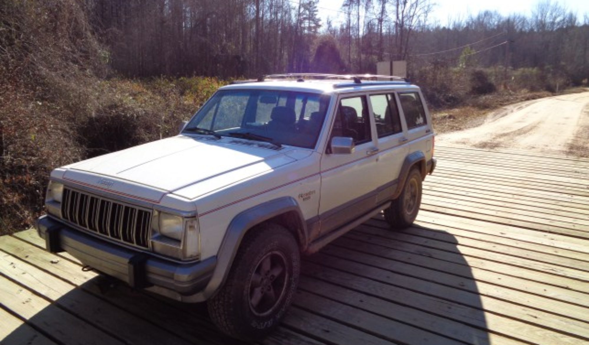
On my Rally Jeep, I simply removed the lock plate. However this required removing the steering wheel and using a lock plate removal tool. The Sentra was by far the easiest solution to disabling the steering wheel lock.

Brake replacement on 2006 Honda Odyssey

Brake replacement on 2006 Honda Odyssey


I began with front brakes. I lifted the van and removed the wheel and tire.  The brake caliper is held to the bracket with two bolts with 14mm heads.  I had to use a 17 mm wrench to hold the slider pin to remove the bolt from it.  Since I was also changing the rotors, I then removed the bracket that holds the pads.  It was easy to just leave the pads in the bracket and take them out once the bracket was off the hub.


The rotor is held to the hub by two Phillips head screws. I had to use an impact driver to loosen them. One still stripped out and had to be drilled.


I put on the new rotor which was first cleaned with brake cleaner. I then put the screw back in to hold it to the hub.  The rotor will only fit one way due to the arrangement of the small screws.


I then put the new pads in the bracket and bolted it back in place.  In order to press the pistons back into the caliper, I used an old brake pad and two C clamps. Once the piston was pressed back in, I reinstalled the caliper. I then replaced the wheel and moved to the other side.


Wheel nut torque is 95 ft lbs


The rear is very similar just smaller. The caliper bolts have 12mm heads.  I removed them the same way as in the front and again left the pads in the bracket as I removed it.  The rear rotors have the emergency brake pads inside so make sure the emergency brake is off before trying to remove the rotor.  The emergency shoes looked fine on this van so I did not replace them.


I put new pads in the holder and bolted it in place. The rear calipers are single piston so pressing them back in is easier than in the front.  with the caliper sand wheel bolted back on, I was nearly done.


Before putting he van in reverse, I pumped the brakes to take up the slack caused by pressing the pistons back into the calipers.  Once on the road, I did five careful slowdowns from 30 to 5 being careful not to come to a complete stop.  I then accelerated to 45 and made to more aggressive slows to 5.  I could then feel the pads biting more indicating that a transfer layer had been formed on the new rotors.

Fuel door release VW Passat

Jennifer’s fuel door suddenly without warning failed to open.  Unfortunately she was out of gas and had no warning before pulling up to the pump.

On her 2000 model B5 the gas lid release is located in the trunk behind a carpet like cover.  The is a small plastic screw that holds the cover in place.

With the screw out, the carpet can be pulled away enough to reach the actuator. Using two fingers, you can pull the actuator back to release the fuel flap.

Testing it in the shop, I found that with the connector off the actuator there was 12 volts when the button was pushed,. However with the actuator in the circuit there was no power.

I removed the actuator and tested it on 12V it worked fine.  Based on internet research I suspected the button in the door.  I removed the door panel and tested the switch. It was fine the voltage was being lost before the switch.  After attempting to find the power source for the circuit, I gave up and jumped power from the courtesy light circuit which was nearby.

She can now put car in her car again without having to open the trunk.

DIY home piston notching

DIY home piston notching


A race engine was brought to our shop after a failure. Before reassembling the engine I decided to check the piston to valve clearance since this was a hybrid engine using an older head on a newer block.

We placed modeling clay on top of the piston, bolted the head in place and timed the cam.  Then we carefully rotated the engine two turns.  We took it all apart to measure the thickness of the clay to determine the clearance.  However, there was no need to measure as the clay had been cut by the valve indicating there was already some slight contact between the valve and piston.

We carefully examined the old pistons from the failed engine and sure enough when we knew what to look for, there were impact marks on the tops of the pistons.  We determined that notches were needed to be cut in the pistons to make the engine runnable.

We came up with the idea to use an old valve coated with abrasive grit to do the cutting.  After some internet research, this was found to be an acceptable practice.   We did some research to see what had worked and what had not.

I repaired the damaged head enough to use it as a guide for the notching procedure.  We used adhesive backed 40 grit sandpaper cut slightly larger than the valve and pressed in place.  In order to get the paper to stick, we had to wire brush the valve face, clean it with brake cleaner and then use a piece of duct tape to remove the last bits of dust off the face.   The sandpaper held pretty well when this process was followed.

We put the valve in the old head and use a drill to spin the valve stem. We gave up on the idea of using a collar to measure the depth cut and just made the cut in several small steps.  We did not bolt the head on just used the dowel pins to locate it on the block.  This allowed up to lift the head easily and check the progress of the cut.

To reduce the amount of metal shavings left in the engine, we used masking tape to seal off the top of the piston being cut.  When the head was lifted off, we used a shop vacuum  to clean up before removing the tape.  We simply cut through the tape rather than trying to predict where an opening was needed.

After we had determined the amount to cut by repeating the clay molding process, we moved to the next piston. We found that the best way to keep the clay from sticking was to have the piston top as clean and smooth as possible. Using oil or WD40 just made it stick worse.  We used a dremmel to smooth the cuts made by the sandpaper on the valves.

By using a valve to cut the notches we assured ourselves that the notch was in exactly the right place to clear the valve and at the correct angle.  Making these cuts on a milling machine would have involved tearing down our fresh short block and collecting data on the center of the desired cat as well as the angle.  Our DIY method eliminated al lot of these variables as well eliminating the expense of the machine work.  The results looked fantastic. Time will tell how well it performs but I expect it will work well.

DANA 30 ARB refresh

Dana 30 ARB refresh

Lessons Learned

My ARB was not staying locked. I could tell by the constant cycling of the compressor that there was an air leak.  I also noticed that it was blowing oil out the pinion seal.

I began by dropping the cover.  I tested the locker and quickly found that the copper air line was cracked right where it is soldered into the air ring.

I pulled the axles and drive shaft to prepare for work on the differential. When I removed the drive shaft, I noticed that the pinion had a lot of slop in it.  I had never noticed it before because at full droop, the driveshaft is fully compressed and puts pressure on the pinion making it feel tight.  Once the drive shaft was out, I could see there was a lot of wear in the bearing. This was the cause of the seal leak.

I also found that when the caps were removed, the carrier just fell out. That meant there was no preload on the gears. This allowed the air ring to rotate flexing the copper tube until it broke. Inspection of the bearing races showed them to be worn and pitted.

I have swapped differential bearing before with my Harbor Freight bearing splitter but I decided to step up this time and get the Yukon bearing puller. I found a well-made clone on Ebay for about half the price of the real Yukon.  It is made in the USA and worked great.  In fact it is so easy to use; I wish I had bought one years ago.

I ordered a Timken Differential bearing kit from Autozone.  It comes with pinion bearings, carrier bearings, a pinion seal, a pinion nut, marker compound, and RTV to make the seal.  At the time I did not realized that the ARB uses different carrier bearings. The instructions plainly say use Timken part # LM102949 / LM102910.   I also ordered new O rings and a new oil baffle as I don’t know how to replace the inner pinion race without destroying the baffle. Morris seems to be the only people who sell this part at a reasonable price.

I was able to solder in a replacement copper tube into the steel air ring. I also installed new O rings in the Air Ring or Seal Housing Assembly as ARB calls it.

I used the Yukon puller and the red clamshells to pull the pinion bearing. I was amazed at how easy the puller made the job.  I then used my old Harbor Freight bearing splitter to hold the new bearing as I pressed in on the shaft.  I used a brass punch to remove the pinion races from the housing.  I used my Harbor Freight bearing driver (the blue one) to install the new races and a new oil baffle.  I then put the pinion in place without the seal and reused the old shims to check the preload. It measured out in spec so the original shims must have been about right.

I then moved to the carrier. I quickly pulled the carrier bearings using the Yukon puller. I then set up the press to install the new ones.  That is when I realized that the bearings on the ARB carrier were not the same as the ones in the kit.  I got really confused for a while.  I took the bearings that came off the carrier into Autozone and the very helpful counter guy pulled out the huge Timken manuals and eventually matched up the numbers.  They actually had the parts in stock as well.  Thank goodness someone still knows how to use the paper manuals.

Armed with proper parts, I pressed on the new bearings and began to try to sort out the shims. I realized that while I had kept the two shim packs together, I no longer knew which side they went on.  I made a guess and pressed on. Not having a case spreader, I had to work out a way to tap the carrier into place.  With the shims being outside the bearings on the ARB, this is much more difficult than with the stock carrier that has the shims under bearings.

I had to pause and refer to the directions to confirm that the shims actually go between the air ring and the bearing on the left side. This makes it easier to handle but concerned me that the O ring gets very near the end of the hub.

I set the carrier in place with left shims in and loosely fit the bearing cap. I then pushed in the right side shims. I then tapped in the master shim with a hammer.  This combination seemed to properly preload the set.  I then set up my dial indicator and measured the backlash. This measurement confirmed what I could feel by hand, the backlash was too much.

I then removed the assembly and swapped the shim packs side for side.   This change put the O ring even more uncomfortably close to the end of the hub. However, once I got it all back in the housing, the backlash was about right.  I called it good and tightened the caps to the correct torque setting.

I then routed the copper tube to the hole in the top and reconnected the blue plastic line.  I then fired up the compressor and tested the locker. It locked and unlocked and there were no audible air leaks.

I then removed the yoke and installed the new pinion seal. I put on a new pinion nut and tightened it down.

I then reinstalled all the other stuff and took it for a test drive.  The locker stayed locked and the compressor ran very little.  I think it is all good now and I am looking forward to my next trip to the rocks.